Pressure reducing valves
A pressure reducing valve is a control valve that reduces the input pressure of a fluid to a desired value at its output.
The maintenance of output pressure or the reduction of input pressure is achieved at a set valve, which is below the charging pressure available in the main circuit. It is thus possible to reduce the pressure in one part of the system to a level lower than main pressure.
Principle of pressure reducing valve
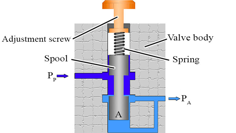
In accordance with the task of the pressure reducing valve not to let the output pressure is fed to the end control element and compared there with the force set at the spring.

If the hydraulic force Fp=Pa*F exceeds the set spring force Fs=c(x+x0), the spool moves upwards in the closing direction of the control lands. Un the control position the spool is force balanced (Fp=Fs).
At he control land, dependent on flow Q and input pressure Pp, an opening is produced which is required to keep Pa constant.
Direct operated pressure pressure regulator
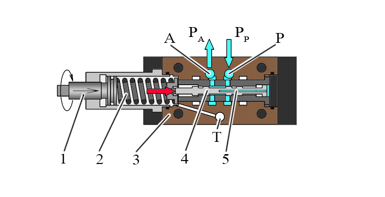
Initially the valves are open, that is there is free flow from channel P to channel A.

At the same time pressure in channel A acts via control line on the spool surface opposite to compression spring.
If the pressure in channel A exceeds the value set at spring 2, spool 4 moves to the control position and keeps the pressure set in channel A constant.
Signal and pilot flows are taken internally from channel A via control line 5.
If the pressure in channel A continues to increase duo to the effects of external forces on the actuator, control spool is pushed further against spring. Channel A is connected to tank via control land at control spool.
Leakages from spring chamber are always returned externally via channel T.
Pilot operated pressure reducing valves

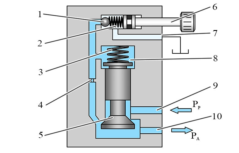
The pressure to be controlled present in channel A acts on the bottom of the main spool 3. At the same time, pressure acts on the spring loaded side of main spool via orifice 4 and on ball 1 in pilot valve channel.
Depending on the setting of spring 2 a pressure builds up in front of ball and in spring chamber 8. This pressure keeps the control spool in its open position. If Pa reaches the pressure set at spring, the pilot valve reacts, ball 1 move off its seat.
Pilot fluid flows from the valve output via orifices and to the pilot valve. The pressure drop existing at the orifice acts on the control spool in the main stage and moves the main spool against the spring. The desired reduced pressure is obtained, once a balance is present between the pressure in channel A and the pressure set at spring.